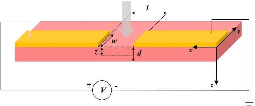
Steady-state photocurrent spectroscopy is a conventional light modulation technique, which measures the photoexcited current in function of the incident photon energy; thus, allowing the investigation of the electronic structure of semiconductors. In this technique, a photoconductor is excited by a continuous stream of photons, generating charge carriers that move and are collected at the electrodes under an externally applied electric field F (Figure1) .
Photoconductivity measurements provide direct evidence of carrier transport and recombination phenomena upon photogeneration. The magnitude of the conductivity change induced by irradiation depends upon the number of carriers produced per absorbed photon (carrier generation quantum yield) and the mobility of photogenerated carriers. Optical absorption of incident light generates the free charge carriers and the electrical transport of these free carriers contribute to the overall current.
The photocurrent action spectrum can be obtained by measuring the photocurrent with respect to the wavelength of incident light. One of the figures of merit for photocurrent measurements is the responsivity(R)to a certain light wavelength:

which can also be understood as normalized photocurrent per incident light intensity.
Setup-Guide: Steady-state photocurrent Spectroscopy
Author:
Majid Panahandeh (PhD NTU 2014)
At a glance: • Knowledge article • Method •Setup
+Steady-state photocurrent spectroscopy +Light Modulation +Diffraction Grating
Contents
1. Application of photoluminescence
2. Why photocurrent measurment
3. Technical tips
4. Other applications
Application of Steady-state Photocurrent
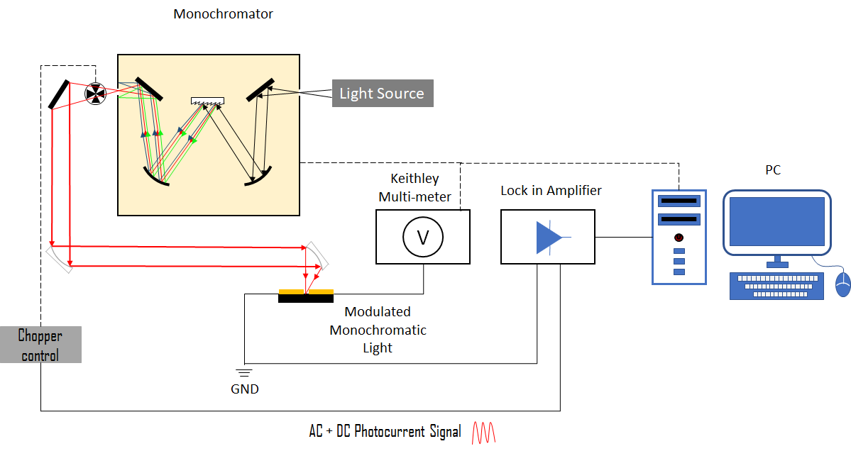
Photocurrent measurements in the visible and near infrared can be done with light modulation and phase-sensitive detection (Lock-in amplifier) technique. All the measurements are computer controlled with different customized LabView programs. Steady-state photocurrent and external quantum efficiency measurements in the range of 200-5000 nm can be performed using a dispersion spectrometer, lamp sources, calibrated photodetectors, and conventional modulation techniques. The steady state photocurrent setup consists of:
-Light sources,
-Monochromator
-Voltages source
-Mechanical chopper
-Optional current preamplifier
-Lock-in amplifier
-Probe station
-Optional vacuum chamber
In this technique the photocurrent is generated using a monochromatic light beam, which light modulated by a mechanical chopper. The modulated light is then focused onto the sample, generating AC photocurrent signal. This photocurrent signal is filtered and detected by a lock-in amplifier.

Figure 1: Device geometry for photocurrent measurement: coplanar stripline with typical dimensions labeled.
In Figure 2, white light from the light source is dispersed by the grating of the monochromator, and the output single-wavelength light beam is collimated and then focused at sample surface by a pair of parabolic mirrors. A voltage source is used to electrically bias the sample. Although the resulting currents from the sample consists of both photocurrent (AC) and dark current (DC), only the AC photocurrent with the same frequency as referencing mechanical chopper frequency is selected and amplified by the lock-in amplifier. The output DC signals are finally collected by a digital-analog acquisition card and recorded by the computer. The two channel output signals from the lock-in amplifier can be either in the form of R and θ or in the form of X and Y. And they are linked by

and

where R is photocurrent amplitude, θ is photocurrent phase shift angle respecting to the referencing signal and X, Y are referred as in-phase and out-of-phase signals. The responsivity (R) of a sample is its photocurrent amplitude normalized with the incident light intensity (I0). Therefore, incident light intensity needs to be calibrated for each time of photocurrent measurement. This can be done by first measure the photocurrent of calibrated photodiodes, usually Si diodes for the spectral region of 240 nm to 1100 nm and Ge diodes for the region of 800 nm to 1500 nm. The incident light intensity is then calculated using the calibrated responsivity (Rd) data sheet of photodiodes

where id dis the photocurrent of photodiodes, Sd is the active area of the photodiodes when light beam is larger than the active area of photodiodes, or it should be the area of the beam spot. Then the actual responsivity of samples is calculated following,

where is is the photocurrent of samples, Ss is the active area of samples when the light beam is larger than the active area of the sample, or it should be the area of the beam spot.

Figure 2: Steady-state photocurrent measurement setup. The optical elements and light beams are represented by thick solid lines, while electrical connections are represented by thin solid lines.
Why photocurrent measurment
Photoconductivity or photocurrent measurements probe the nature of the charged photoexcitations of a system yielding information about:
-Exciton-charge conversion
-Charge mobility
-Charge carrier lifetime
Technical tips
Samples can be measured either on a probe station equipped with four probes or in a built high vacuum chamber. The high vacuum chamber with two electrical feedthroughs can be used for either low temperature measurements or for preventing samples from degrading as in ambient air. Using different excitation sources will enable us to investigate variety range of materials over a wide range of spectrum from MIR to visible to UV region, while cryostat provide means to control the surrounding temperature between 77 and 500 K. In addition, CW lasers of different wavelengths can provide higher light intensity than white light source for steady-state photocurrent spectroscopy measurement, which is useful for light intensity dependent photocurrent measurement.
Other applications
This technique can be reconfigured for many other electrical and optoelectronic measurements, such as:
-The I-V curve measurement with and without light illumination
-The characterization of transistors (output and transfer curves)
-Photo-transistor measurements
With customized components, frequency dependent, light polarization dependent photocurrent measurement can also be done with this setup.