Abstract: In a common optical path structure, the optical path is often restricted to propagate in the plane, and the optical height (the distance between the axis of the optical path and the optical platform) is generally a certain value. For some more complex optical paths, due to the use of spatial structure, polarization conversion, and optical components, the design is not limited to the same height of the plane, but to become three-dimensional, so that the conversion device of the light height must be used optical climbing high/low mirror. How to design and use optical climbing high/low mirror safely and accurately is what this article will introduce to you.
I. The common use of climbing
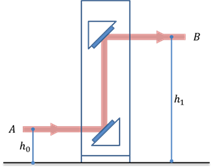
Figure 1. The basic structure of the climbing mirror
Figure 1 is the basic structure of the climbing low mirror (due to the reversible reversal of the optical path is the climbing low mirror), the light path is horizontally incident at the climbing mirror at A, and is collimated and exits from B, the light height is increased from h0 to h1, while the direction of light propagation is unchanged. So, what steps do we need to pay attention to so that we could get the appropriate light height and collimated light path? Here are summarized as the following two aspects:
1. Optical Climbing Design
2. Adjustment and calibration of climbing high mirror (including safety regulations)
(Note: Please pay attention to reading the safety specifications section. Statistics show that a considerable number of eye injury experimental accidents occurred during the process of irregularly installing the climbing frame. It is also not uncommon for the United States to rectify and rectifying national laboratories due to laser accidents!)
1) Climbing design
If you plan to design a climbing frame yourself, then you need to consider whether your design can simplify your calibration steps. Here is a simple solution for reference. As shown in Figure 2, the mirror needs to be placed at 45 degrees to the incident angle, and the actual situation is that it is difficult to adjust the correct angle by manual adjustment, so we design an isosceles right-angle slider here and fix the lens above. As long as we can ensure that the side of the slider is perpendicular to the incident light, we can determine the correct placement angle. We can design such a baffle that is strictly perpendicular to the optical path on the support plate of the climbing frame. At this time, as long as we ensure that the slider fits the baffle, our purpose is achieved. Besides, we can move the slider along the baffle to ensure that the incident light corresponds to the correct position of the reflector. At this time, we fix the slider with screws on the other side of the support plate. The corresponding position on the support plate should be provided with a slide slot to facilitate adjustment and fixation. The second mirror can determine the position according to the same principle. Finally, when your design is complete, please place a light barrier on the top of the climbing mirror, which can greatly reduce the risk of injury to your eyes by the light path.
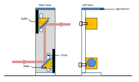
Figure 2. Climbing frame reference
Of course, if you lack suitable processing conditions to help you complete the processing of these parts, you can also use two frames and a support plate (of course you have to ensure that your frames can be stably fixed on it) to temporarily build a climbing elevated structure. How to install under this condition, we will explain in detail next.
2) Adjustment and calibration of the climbing frame
The method mentioned here applies to the condition that both the upper and lower reflectors of the climbing frame can be adjusted in two dimensions of X and Y. As shown in Figure 3, the reflector is fixed on the adjustable frame to complete the adjustment by two knobs. Note that under most conditions, we use a spirit level, or a reticle, as our reference light source for calibration. After you ensure that the climbing frame is adjusted, you can only introduce the collimated light path into the climbing frame. In addition, during the entire process of your adjustment and light guide, it is recommended to wear corresponding protective glasses, and in any case, do not directly observe the light path from above the climbing mirror. When you do this, make sure that you go to the nearest hospital for treatment as soon as possible, and inform your tutor of the possibility of the experiment being closed. In fact, you can carry out your operation at the angle on the right of Figure 3 and wear protective glasses all the way.
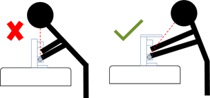
Figure 3. Correct posture for climbing
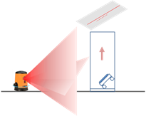
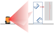
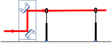
Figure 4. Adjusting method of climbing
After emphasizing the safety issue, we can start the topic. As shown in Figure 4, first of all, we need to make the light of the spirit level positively enter your climbing frame. Here we refer to the light in the two directions of the spirit level as horizontal light and vertical light. Correspondingly, the pitch direction of the adjustable frame is called the vertical direction, and the dimension perpendicular to the vertical direction is called the horizontal direction. Here, the height of the reflector needs to be roughly fixed and adjusted to the height position of the incident light and the emitted light, respectively. Next, we put a piece of white paper on top of the climbing high mirror, which is roughly parallel to the mirror. At this time, a part of the vertical light emitted by the spirit level forms a track on the white paper, and some vertical light passes through the mirror upward on the white paper. Another track is formed on the other side. At this time, the horizontal direction of the mirror is adjusted so that the two tracks coincide, and the horizontal direction of the mirror 1 is adjusted. The adjustment method of the mirror 2 in the horizontal direction is similar. It should be noted that at this time, the light reflected twice may be weak, and a darker environment helps to facilitate the adjustment.
The next step is to calibrate the vertical direction of the two reflectors. Here it is recommended to use a point light source with the same light height as your experiment light, or to adjust your experiment light as much as possible. First, adjust the reflection position of the incident light roughly to the center of the second reflector, and then place a diaphragm at the two positions near the light exit of the climbing frame. The diaphragm height is set to the output light height you need. Here is the familiar adjustment method of the collimated optical path, which is completed by repeatedly adjusting the vertical direction of the two reflectors several times.
Of course, the use of climbing is not limited to the adjustment of the height of the optical path. Here we continue to introduce you to another application of the climber: polarization conversion.
II. Application of polarization conversion for climbing
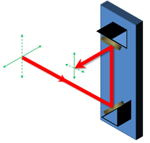
Figure 5. The polarization conversion application of climbing
As shown in Figure 5, the green arrow in the figure represents the polarization direction of the light, where the solid line represents the horizontal polarization and the dashed line represents the vertical polarization. After the conversion of the optical climbing, the light in the original horizontal polarization direction is converted into vertical polarization. The light in the polarization direction will be converted into horizontal polarization so that we can achieve the role of polarization conversion. In this case, our design and adjustment methods are similar to the previous one. It should be noted that due to the role of directional rotation, the corresponding adjustment direction also needs to be rotated. The horizontal and vertical of the reflector corresponding to the incident light adjust the direction, which is corresponding to the vertical and horizontal directions of the outgoing light.